*I turned off and disconnected the Power Supply from the motherboard and video card. Then I removed the video card from the motherboard.
*Removed both sides of the Fratal Design case.
*Remember to use the cable management compartment when routing cables.
4A Power Supply
*Difficulty: Easy.
*Installed the power supply into the case, four screws on back of the case secured it.
*Note the yellow grounding strap hooked to one of the Power Supply bolts.
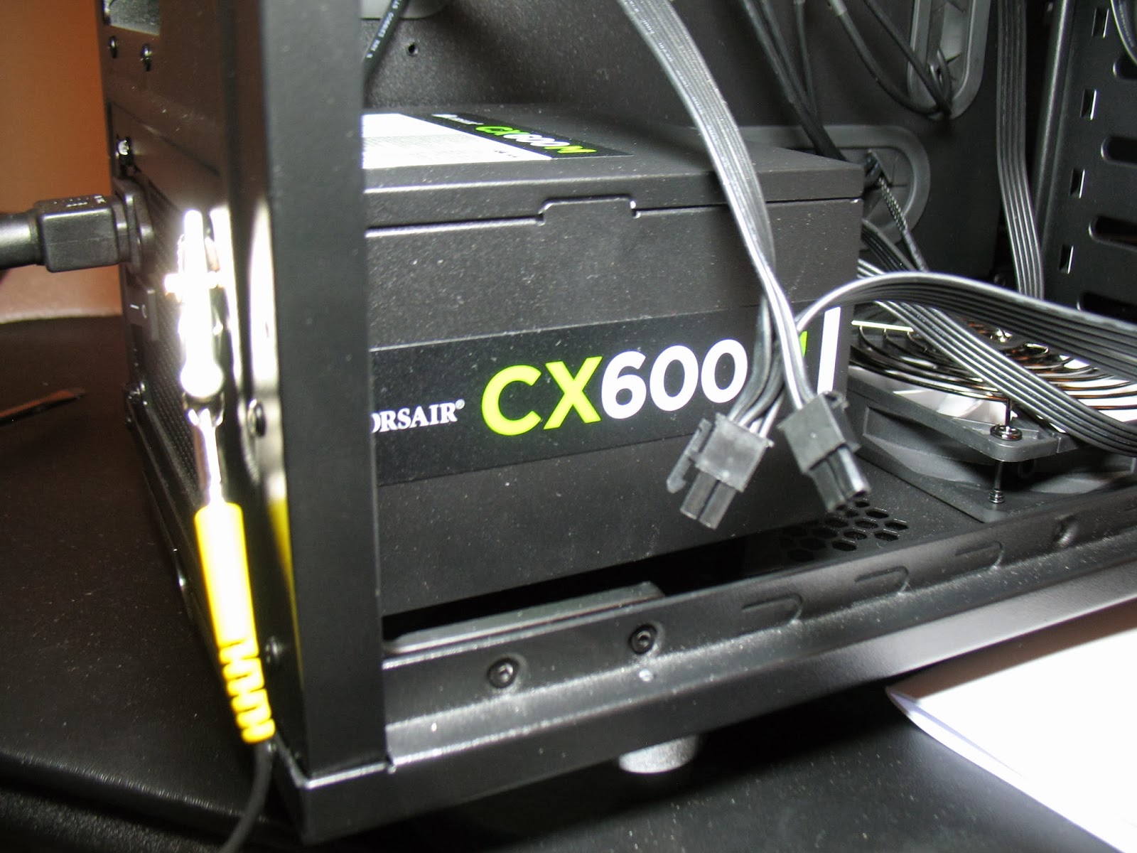 |
| Power Supply Installed |
*Sony AD-728OS-OB
*Difficulty: Easy.
*Popped out the top slot on the front of the computer, slide in the DVD player/burner and installed 4 screws, 2 per side.
4C 1TB Hard Drive Physical Install
*Seagate Barracuda 1TB drives ST1000DM003
*Difficulty: Easy.
*Mounted to quick install tray, mounted on 4 rubber grommets with 4 screws.
*Trays slid and clicked into appropriate slots.
*Electrical Connection later.
 |
| Hard Drive in Quick Install Tray |
 |
| Hard Drive in Appropriate Slot (Images are clickable!) |
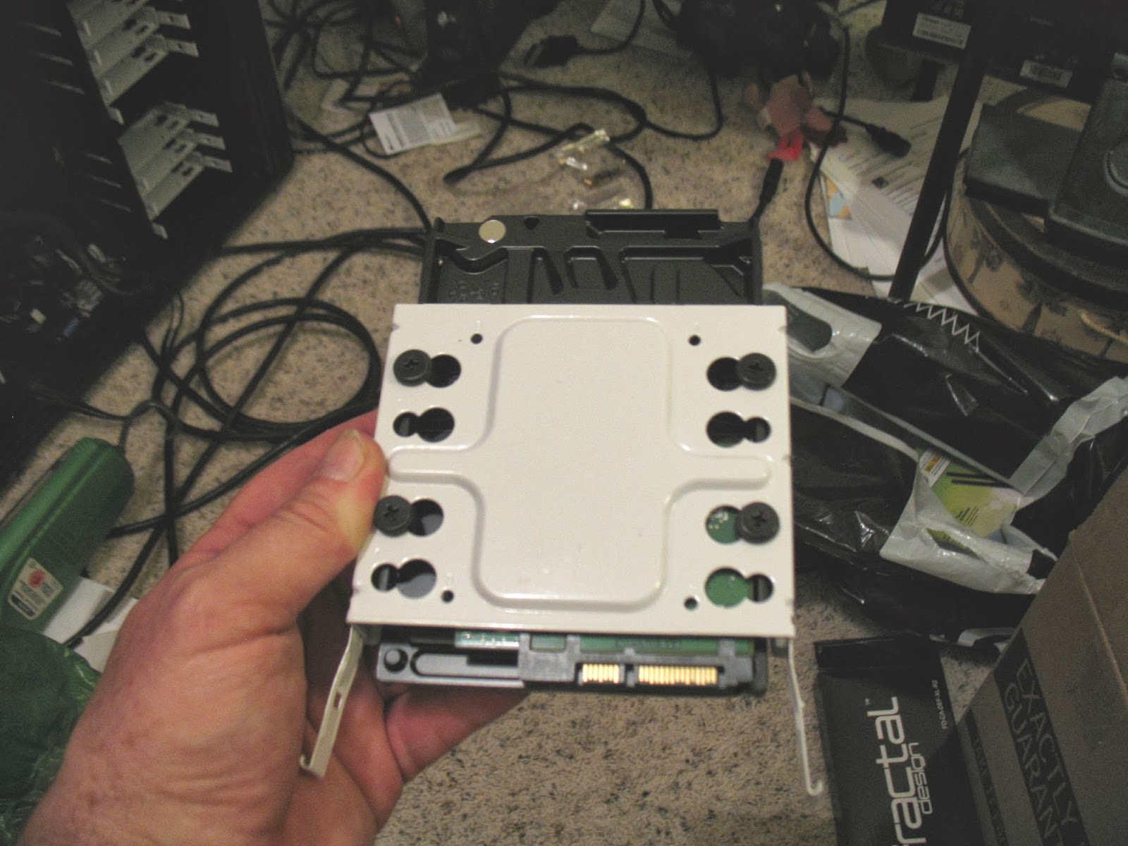
4D 120 GB SSD (Solid State Drive) Physical Install
*Difficulty: Easy.
*Sandisk SDSSDX-120GB-G25- Solid State Drive. This is the new standard for running the Operating System from. Faster than a traditional hard drive, no moving parts.
*Mounted directly to the middle of the tray. Find the aligned holes with 4 small screws that came with the case. Not mounted on the grommets.
*Electrical Connection later.
 |
| Sandisk Solid State Drive |
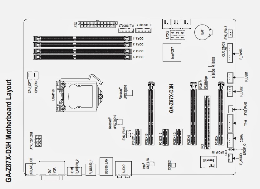
4E Motherboard Physical Install
*Difficulty: Easy.
*Gigabyte GA-Z87MX- D3H
*Caution: Avoid dropping screws onto motherboard. I had one all most get stuck under the CPU cooler bracket.
*Note the pic for section 3F.
*Motherboard Standoff Posts- Determine which holes your motherboard should attach to. Depending on the case, motherboard standoff posts may or may not be installed. These are posts that keep the motherboard away from the case. My case did not have these installed, but were included and they included a black fitting that could temporally be put on the end of a post so a screwdriver could be used to screw them into the case. I figured out which holes and screwed in the standoffs. The holes in the motherboard ment for attachment to the case have dashes drawn around them.
*Input/Output Shield- Before placing the motherboard on the standoff posts, insert the Input/Output shield in the hole at the back of the case where all of the external motherboard connectors are accessed. This is a finished piece of trim that surrounds the connectors after the motherboard is installed.
*Screw the motherboard to the case.
*Photo Orientation: Most of the motherboard photos and diagrams are oriented in the same direction. In this picture the back of the case is down. The bottom of the case is to the right.
*Notice: Look for the motherboard mounting screws with the radiating dashed lines around them. I spot 9 of them. All of these photos are clickable for a zoomed view.

 | |
| Standoff Posts (not installed) |
4F H55 Cooler Fan Radiator Install (in Case)
*Difficulty: Easy.
*Relocated rear fan to top of case and installed fan/radiator into existing bolt holes on back of case.
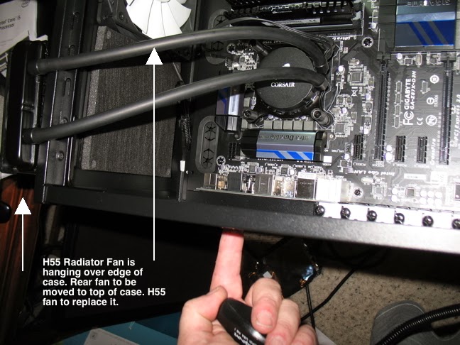 |
| H55 Being Installed |
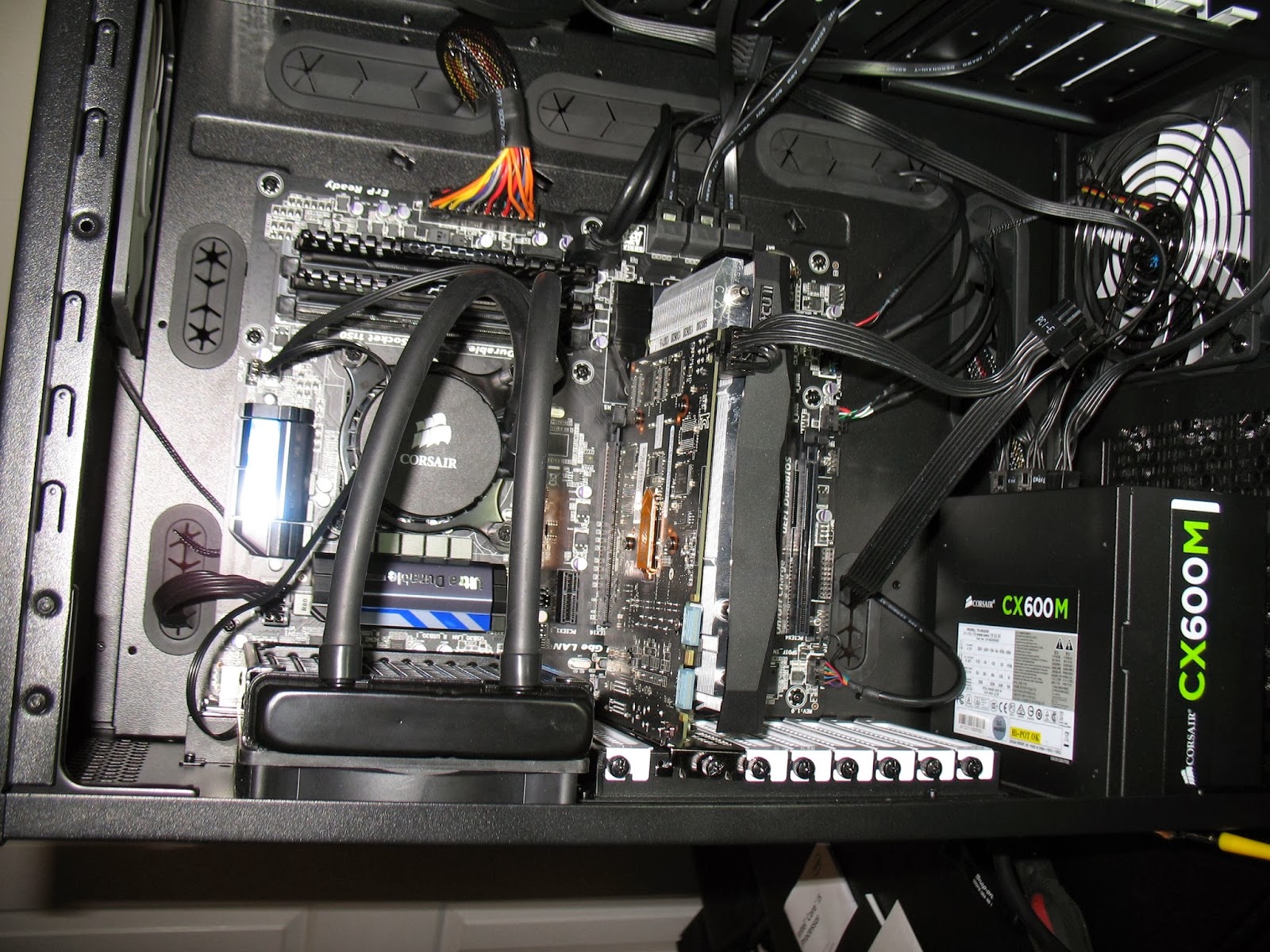 |
| H55 CPU Cooler Installed. Fan Radiator mounted on back of case. |
*Notice the main motherboard power connection (orange/yellow wires) in this picture above the CPU/Cooler.
4G Mobo electrical hookup in General
*If the paper manual is crap, hopefully your motherboard maker has a better one online to download. In my case, Gigabyte did.
 |
| The Value of A Good Diagram |
*Compare the photo to the diagram (above). The Main Power Cable in the graphic below is the large orange and yellow connector.

*This closeup of the CPU Aux Power is coming from the Power Supply through the Cable Management Compartment. It's not yet hooked up to the connector marked ATX 12v that is partially obscured by the power to the H55 Cooler fan.

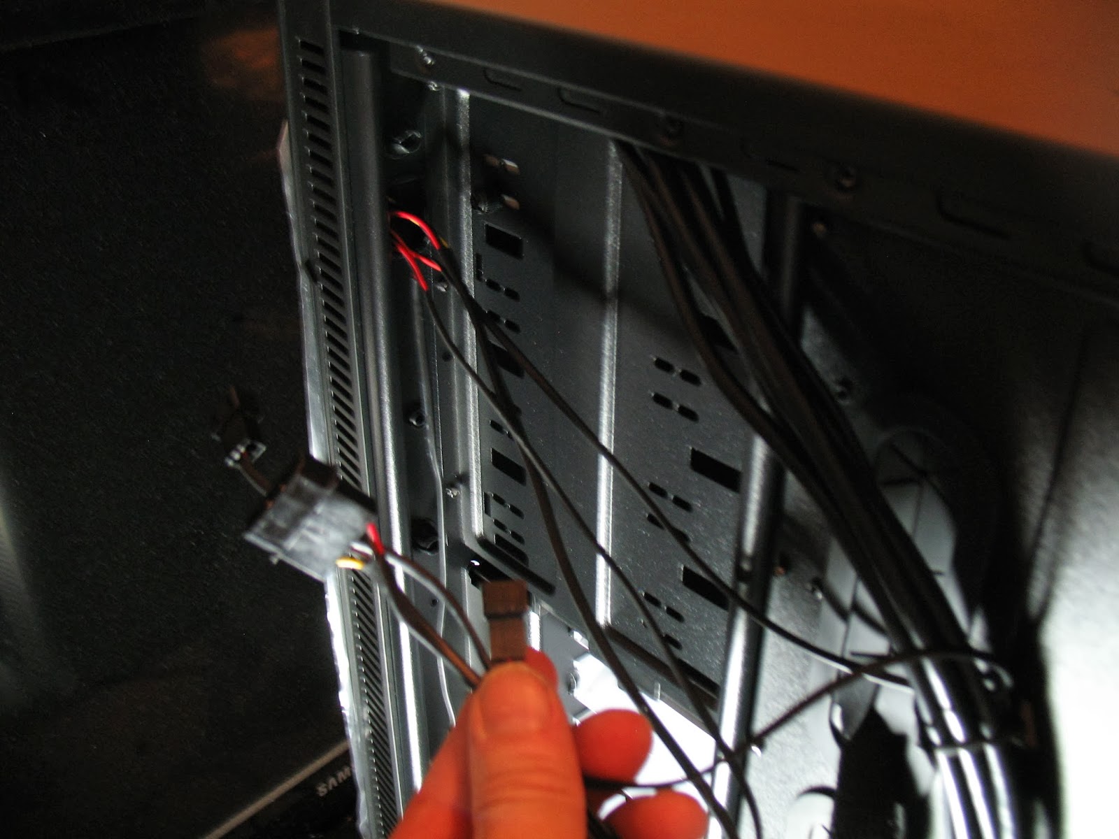
4H Fan Electrical Connections
*Difficulty: Possible questions about connecting which leads to which case connectors
*Picture Description- Ok, so this is a pretty crappy picture from an illustrative standpoint, but it is in the vicinity of the top front, side of the case viewed from the cable management compartment. The individual wires are to connect to the individual fans. A single molex connector is used to power them (from the Power Supply) through the master fan switch this case has on the top front of the case.
*As in the video, this case includes a Master Fan Switch on the front of the case. So from the vicinity of this switch is a dangling power connector and 4 fan connection leads. The idea is that power is routed through the main switch, to each fan. So I hooked up a power supply lead with the appropriate size plug to the fan switch, and then connected all 3 fans, excluding the cpu cooling fan, to the fan switch leads. This particular lead included '''4 pin molex straight line connectors''', but it ended up only connected to the master fan switch.
 |
| Fan Connections |
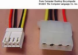 |
| Molex Connector |
*Difficulty: Figure out what goes where. Physically not difficult.
*Photo Orientation: The back of the case is to the left. The bottom of the case is down. Note the power supply.
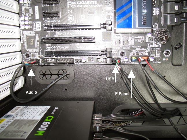
*A variety of single pin hookups to the motherboard. These cables are in the case and marked. Use the motherboard install manual for reference.
*PW- Power Switch.
*PLED- Power LED.
*RES- Reset Switch.
 |
| Image is Clickable! |
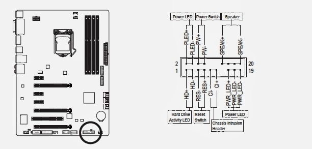 |
| F Panel Diagram |
4J Misc Hookup
*Difficulty: Figure out what goes where. Physically not difficult.
*Cables in case and marked. Use motherboard manual for reference.
*HD Audio
*USB 3.0
*Check out pic (above) "F Panel, USB, Audio".
4K DVD Electrical/Data Connection
*Difficulty: Easy.
*Requires both power and (SATA) data cables.
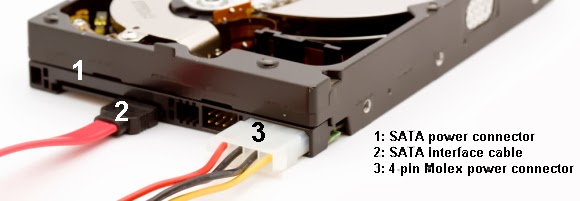
*For power, DVD drive '''may have both SATA and Molex Power connectors'''. Use the one that is most convenient.
*Pick appropriate power cable from power supply.
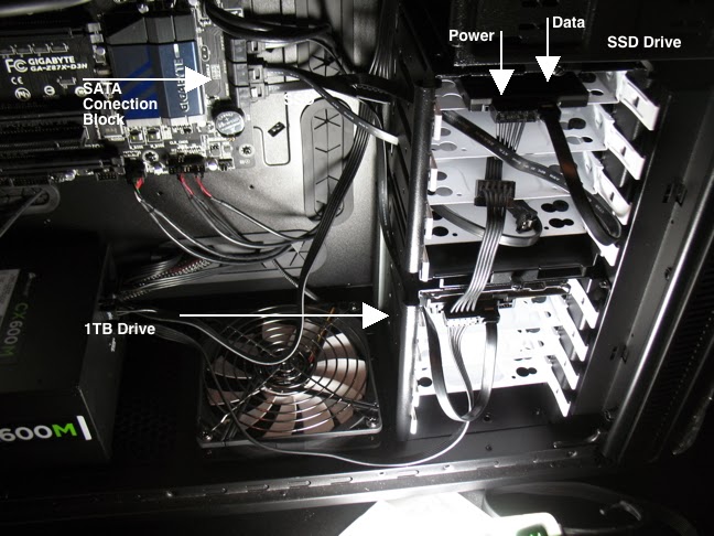
*SATA data cables are individual connections. Each SATA device gets an individual cable to connect to the motherboards SATA block.
*Pick SATA data cable and connect DVD to SATA block on motherboard. I have no idea if this makes a difference, but I connected the DVD drive to SATA Port #4.


4L SSD and Hard drive Hookup
*Difficulty: Easy.
*Reference the Sata Pics above.
*Requires both power cables and (SATA) data cables.
*1TB Drive may include a '''Molex Connector''' power connection in addition to '''SATA''' power connection. Check your Power Supply cables to verify which power cable to use.
*Check your motherboard package for SATA data connections.
*SSD drive connected to SATA Port #0.
*1TB hard drive data connected to SATA Port #2.
 |
| SATA Power and Interface Cables |
4M Wireless Network Card
*Difficulty: Easy.
*TP-Link TL-WDN4800.
*Installed in PCI x1 Slot, a very small slot.
---End of Part 4---
No comments:
Post a Comment